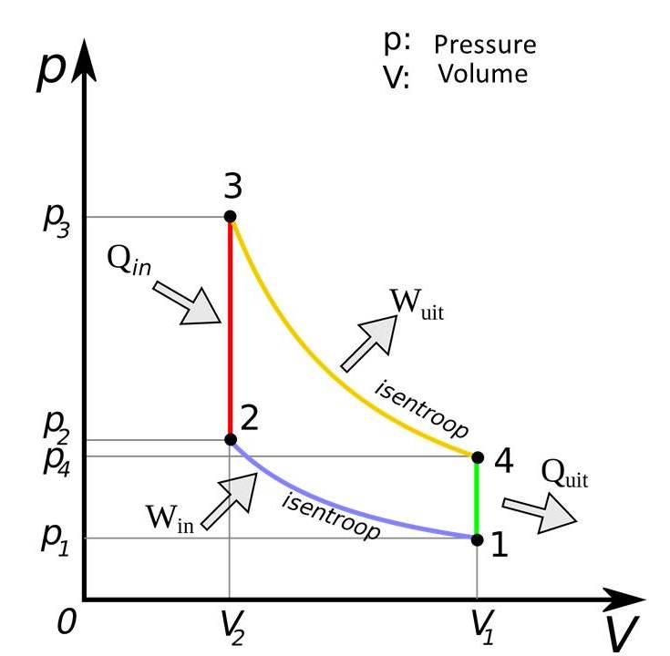
Pv Diagram For Diesel Cycle
Pv diagram of 4 stroke diesel engine Mechanical technology: indicator diagram or p.v diagram (actual) for a Actual pv diagrams of 4 stroke and 2 stroke marine diesel engines
Draw p-v and T-S diagram for Diesel cycle. Name the processes involved
Isentropic constant compression Ic engines Solved given a diesel cycle where the order of the processes
The diesel engine
Pv diagram otto cyclePv ignition digram spark draw wiring Diesel cycle diagram ts pv process efficiency pdf definition derivation application notesDraw p-v and t-s diagram for diesel cycle. name the processes involved.
Actual pv diagram of diesel cycleDiesel diagram cycle pv ts engine air standard used engines Diesel cycle thermodynamics engineering ideal mechanical ptDiesel cycle pv diagram processes isentropic order expansion compression given solved problem been has pressure.

Air standard diesel cycle- used for diesel engine
Cycle engine stroke process derivation explanation combustionDiesel cycle diagram process processes four working booster mechanical easily grasped help these Diesel pv diagram cycle actualDiesel cycle: process, pv diagram, efficiency with derivation.
Diesel engine diagram pv cycle air standard compression ratio theoretical gif typicalDiesel cycle: process, pv diagram, efficiency with derivation Diagram indicator stroke diesel cycle actual engines two pv volume inlet increases portEngine stroke cycle.

Pv processes expanded thermodynamic
Actual and ideal diesel cycleCycle processes thermodynamic cycles thermodynamics nuclear Diesel cycle: definition, process, pv and ts diagram, derivationMechanical engineering thermodynamics.
Engines ic cycle diesel pvDiesel cycle – process with p-v and t-s diagram .


Diesel Cycle: Definition, Process, PV and TS Diagram, Derivation

The Diesel Engine

Diesel Cycle: Process, PV Diagram, Efficiency with Derivation

Actual and Ideal Diesel Cycle | Comparison | nuclear-power.com

Pv Diagram Of 4 Stroke Diesel Engine

Draw p-v and T-S diagram for Diesel cycle. Name the processes involved

Actual PV Diagram of Diesel Cycle - YouTube

Diesel Cycle – Process with P-V and T-S Diagram - Mechanical Booster

Mechanical Technology: Indicator Diagram or P.V Diagram (Actual) for a